A/C help

RonJ

Banned
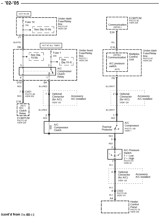
where does the blue wire after the pressure switch go or come from ? What is the direction of flow there?
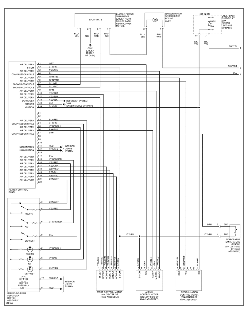
The blue wire runs to the heater control panel/A/C button. Voltage flows from the ECU to the MCU to the heater control panel. When you press the A/C button, the voltage is grounded. The ECU senses the grounding of its voltage and then activates the fans and clutch.

Also the one above? And last the blk yellow wire come from where and goes to where?
Not sure what you are asking here.
 

duke9074

New Member


in this image the yellow wire top right corner connects under dash fuse box to what the wire simply runs off the image and never returns..... Same with the blue wire leaving the right side of pressure switch in bottom right of the box... once again same with blue/white wire leaving blower motor


duke9074

New Member
MCU looks to be one in the same with the under dash fuse box


RonJ

Banned
in this image the yellow wire top right corner connects under dash fuse box to what the wire simply runs off the image and never returns..... Same with the blue wire leaving the right side of pressure switch in bottom right of the box... once again same with blue/white wire leaving blower motor
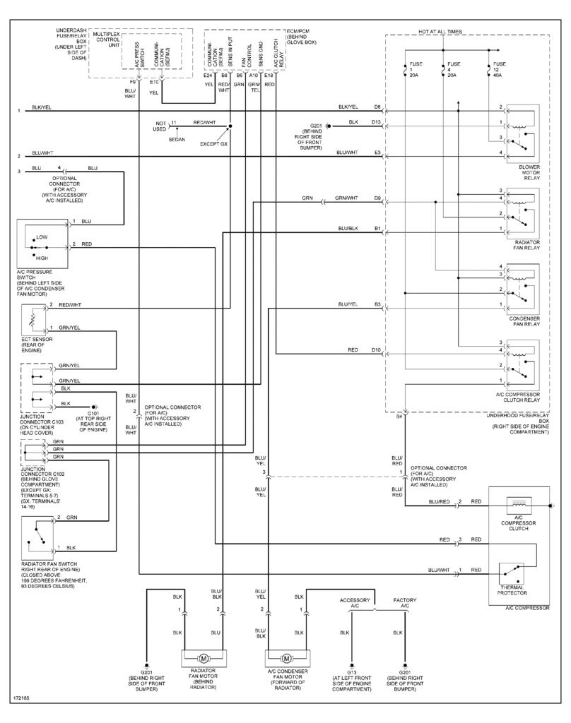
Here is the complete circuit diagram:


duke9074

New Member
IF i am reading this right the blue wire from pressure switch to heater control module should be 12v until its grounded at heater control module?

blue and white wire should never be in 3pin compressor connection according to diagram?

and the red wire is still a mystery?
 

RonJ

Banned
IF i am reading this right the blue wire from pressure switch to heater control module should be 12v until its grounded at heater control module?
Correct

blue and white wire should never be in 3pin compressor connection according to diagram?
Not sure. The diagram doesn't show connectors or how wires are routed.

and the red wire is still a mystery?
Correct. But I think we may be able to pinpoint the problem without solving this mystery.
 

duke9074

New Member
well we know red wire connects compressor to pressure switch? mystery is why lol

can a self diagnoistic for mcu be performed?
 

RonJ

Banned
well we know red wire connects compressor to pressure switch? mystery is why lol
We'll figure it out. Did your A/C problem coincide with any recent car work?

can a self diagnostic for mcu be performed?
Yes. But first finish a few basic tests, like the one I mentioned, which should eventually rule out or point to the MCU.
 

duke9074

New Member
no recent car work. im usually quite handy weakest point being electrical ofcourse its my problem ask me to assemble a motor fine make a complex wiring diagram or harness and well it anit happening...... quick answer is no but a/c was recharged about 18 months ago and filled and continued to work till about 2 weeks ago.....
 

RonJ

Banned
no recent car work. im usually quite handy weakest point being electrical ofcourse its my problem ask me to assemble a motor fine make a complex wiring diagram or harness and well it anit happening...... quick answer is no but a/c was recharged about 18 months ago and filled and continued to work till about 2 weeks ago.....
Okay. Do the next grounding test mentioned above and post the result. My guess is that the MCU is fine.

It appears to me that your wiring is different than shown in the circuit diagram between the MCU and pressure switch.

The diagram suggests the wiring should look like this:

MCU --> Blu/Wht wire --> Pressure switch

Your wiring appears to be modified like this:

MCU --> Blu/Wht wire -->connector??--> Red wire --> Pressure switch

It may help to locate where the Blu/Wht and Red wires come together.
 

duke9074

New Member
i agree my wiring appears MCU --> Blu/Wht wire -->connector??--> Red wire --> Pressure switch

but not convinced becuase if that was so blue/white wire to red jump is turning the system on why?

blue and red wire have to come together at thermal switch the other side of the connector only place all 3 wires go... i found another diagram i think its helpful to us


it clearly shows all 3 wires i have described and confirms the red wire jumps the thermal switch to pressure switch


reading this last diagram make it seem to me the thermal protector is bad but leaves me with one question why when it is jumped does the switch work in reverse it appears jumping it would do nothing more that eliminate the thermal switch...
 

RonJ

Banned
it clearly shows all 3 wires i have described and confirms the red wire jumps the thermal switch to pressure switch
Nice. The diagram clearly solves the Red wire mystery. I've never seen a Civic A/C circuit wired this way.

reading this last diagram make it seem to me the thermal protector is bad but leaves me with one question why when it is jumped does the switch work in reverse it appears jumping it would do nothing more that eliminate the thermal switch...
One interpretation is that you have two separate problems:

1) A bad thermal switch or bad thermal switch red wire
2) A bad heater control panel or an incorrectly wired heater control panel

Do a continuity test to locate the open (no continuity) in #1

For #2, test for continuity to body ground on the blue pressure switch wire with the A/C switch on versus off to test whether it is providing ground when off and no ground when on.
 

duke9074

New Member
You lost me please rephrase that last message I got
Two problems I don't under stand what you mean by part one a bad red wire ? And how to perfor
The tests ?

Bad red wire on which side of connector ? Thermal switch side ?

I also have 2 heater control modules I've swapped both I doubt I have 2 faulty units will check both though

How could a heater control module be incorrectly wired ?
 

RonJ

Banned
Two problems I don't under stand what you mean by part one a bad red wire ? And how to perfor
The tests ? Bad red wire on which side of connector ? Thermal switch side ?
If you unplug the two red wires of the thermal switch, you are left with this:

Red wire --> thermal switch -- Red wire

Current cannot flow from the red wire on the left through the switch to the red wire on the right. The problem could be a broken red wire on the left or right or a bad switch. By testing continuity between various points, you can pinpoint the bad component.

I also have 2 heater control modules I've swapped both I doubt I have 2 faulty units will check both though
That's what I was thinking too.

How could a heater control module be incorrectly wired ?
If you did not alter the wiring, then the control panel may be bad or the replacement panel is not identical to the original (pinned slightly differently).
 

duke9074

New Member
In the 3p compressor connector grounding the blue/white wire causes the whole system to run fans and compressor clutch engaged. Also noted in this setting i have no control over it meaning selecting or deselecting the a/c button has no effect.

Continuity from 2p blue wire to body ground and to battery ground proved no continuity but about 880 ohms of resistance. EDIT performed wrong test will redo tomorrow....... ANd clarification i have been calling the a/c button the heater control module and bleive that is actually the spin dials i also believe this to be my problem switch.


Under dash fuse/relay box connector F pin 9 wire color blue/wht has battery voltage.
 

duke9074

New Member


now we know the location of all the wires so i believe after reviewing this and our work that the blue pressure 2 pin wire should have power ??? and is open??
 

RonJ

Banned
In the 3p compressor connector grounding the blue/white wire causes the whole system to run fans and compressor clutch engaged. Also noted in this setting i have no control over it meaning selecting or deselecting the a/c button has no effect.
This is working as it should, meaning that the problem is downstream of the Blu/Wht wire.

Continuity from 2p blue wire to body ground and to battery ground proved no continuity but about 880 ohms of resistance. EDIT performed wrong test will redo tomorrow....... ANd clarification i have been calling the a/c button the heater control module and bleive that is actually the spin dials i also believe this to be my problem switch.

Under dash fuse/relay box connector F pin 9 wire color blue/wht has battery voltage.
Not sure why you are doing these^ tests. Test continuity of the thermal protector switch.
 

duke9074

New Member
To correct myself I only hve one heater control module and 2 ac recirculating modules..... I thought u wanted me to test that so if not what test should I be performing ? Continuity from 2p to term 4 on heater module which is the dash module with turn dials?


Thermal protector from pin one to pin three has no continuity so it has either a bad wire or bad switch ?

If It is down stream of blue and white it must be upstream of the pressure sensor since neither wire has voltage?


Top